
product · Feb – June 2025
Dual-channel actuation for an olfactory prosthesis
ROSE investigates whether combined stimulation of the nasal cavity can help people recognise smells. I developed its two-channel mechanical stimulation module.
Project details
-
Research on an olfactory prosthesis
ROSE is a European research project exploring an olfactory prosthesis for people who have lost their sense of smell. Several universities and a hospital contribute: one partner develops an electronic nose, the EPFL lab builds a device to stimulate the nasal cavity, and the hospital tests the approach with patients.
-
Combining three stimulation methods
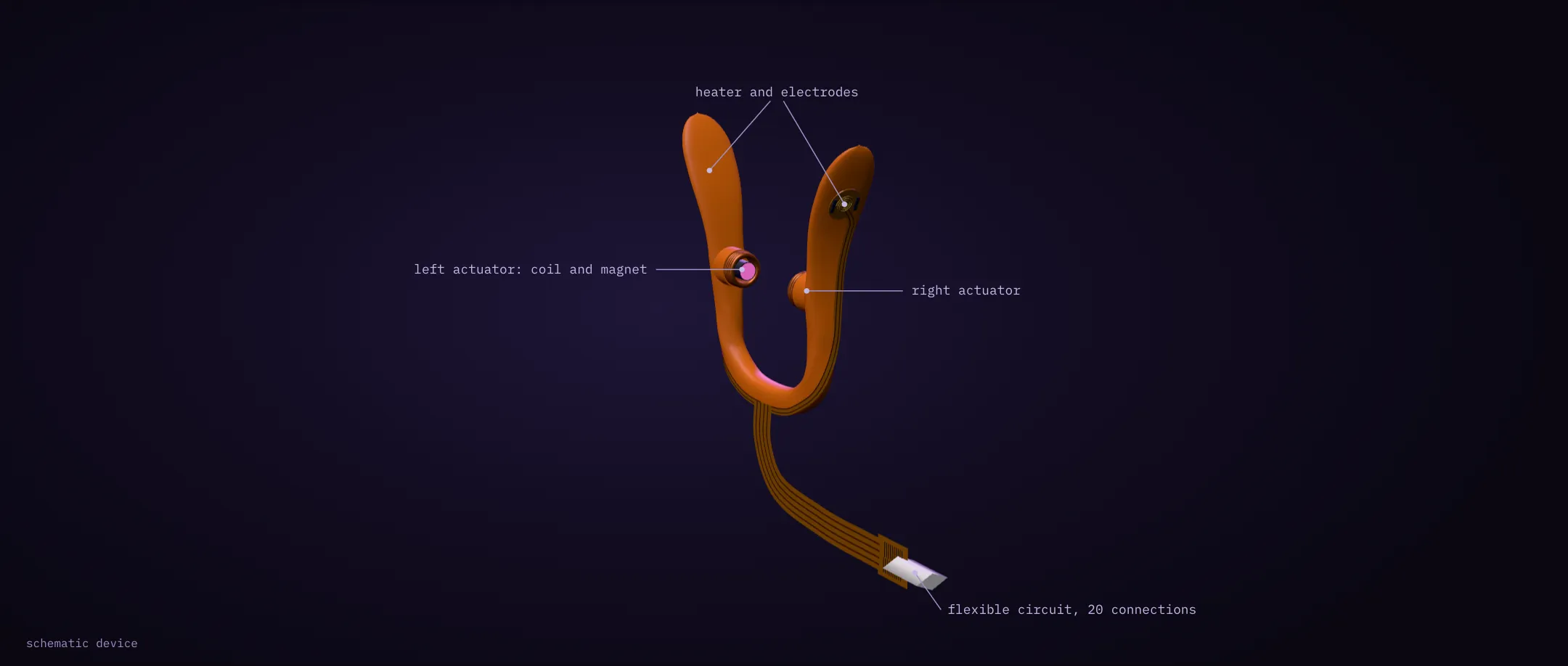
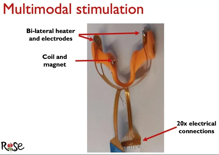
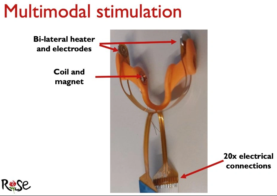
Each nostril receives a heater, electrodes and a coil that vibrates a magnet. The idea is close to a cochlear implant, which stimulates the nerve directly and works better with several channels than with one. Electrical stimulation has shown encouraging results; ROSE investigates whether combining it with heat and vibration can help people recognise smells.
-
Independent control of the two actuators
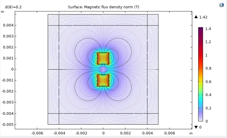
I worked on the mechanical stimulation module, which previously operated on one side only. Testing combinations of stimuli requires independent control of both nostrils. The two actuators also sit close enough for their magnetic fields to interact, so I had to design their drive and their coupling together.
-
Generating the actuator drive with PWM
400 Hz modulation · 62.5 kHz carrier
I generated the drive signals on the microcontroller, with frequency, amplitude and timing set independently for each channel. This reduces the need for external signal-generation equipment and allows the stimulation parameters to be changed in software. The report validates a 62.5 kHz carrier modulated at 400 Hz.
-
Class-D amplifier and output filter
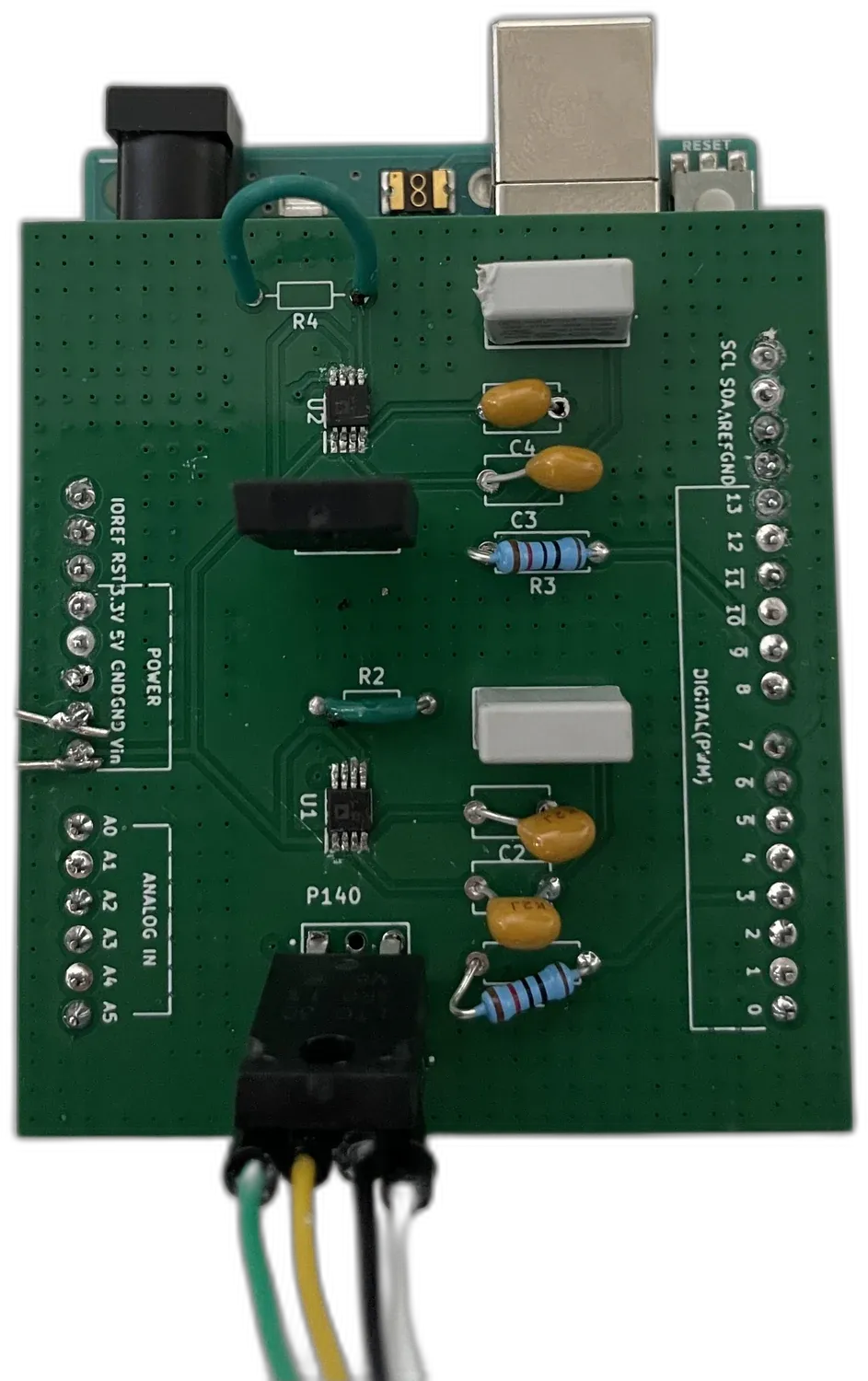
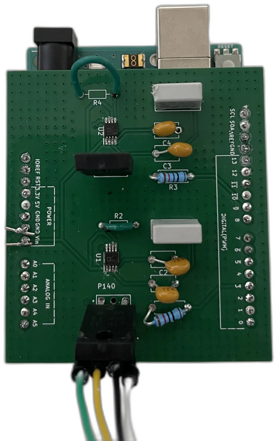
The coils require more current than a microcontroller pin can supply. I designed a Class-D amplifier stage to limit heat dissipation in the small device. Its switching output is compatible with the PWM drive, but requires a filter; I designed that filter as part of the amplifier board.
-
Coil–magnet forces and actuator coupling
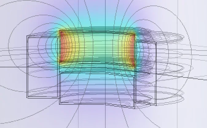
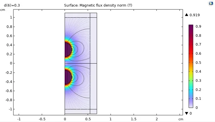
The magnet and coil have similar dimensions, which limits the accuracy of simple analytical force models. I used magnetostatic simulation to compare geometries, calculate force against displacement and assess coupling between neighbouring actuators. Simulated forces included 0.81 mN at 0.4 A and 2.30 mN at 0.8 A; these are not measured values.
-
Validation of independent actuator control
Both actuators operated independently and simultaneously from one board. I checked duty cycles of 30, 40, 50 and 80 %, and bursts of 50 to 500 ms on the oscilloscope. Displacement and efficiency were not measured. For a next iteration, I would define the measurement protocol and coupling constraint before building the board.
Coil–magnet force vs. distance and current
Compare the COMSOL force simulations for three magnet sizes. Adjust the position and peak current to inspect the simulated points.
- Force at selected settings
- 0.81 mN
- 0.8 mm, at 0.4 A
- 0.81 mN
- 0.4 A, at 0.8 mm
- 0.81 mN
- 0.4 A, at 0.2 mm
- 0.43 mN
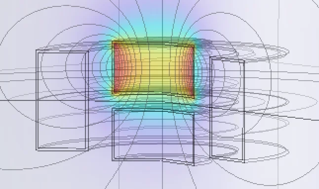
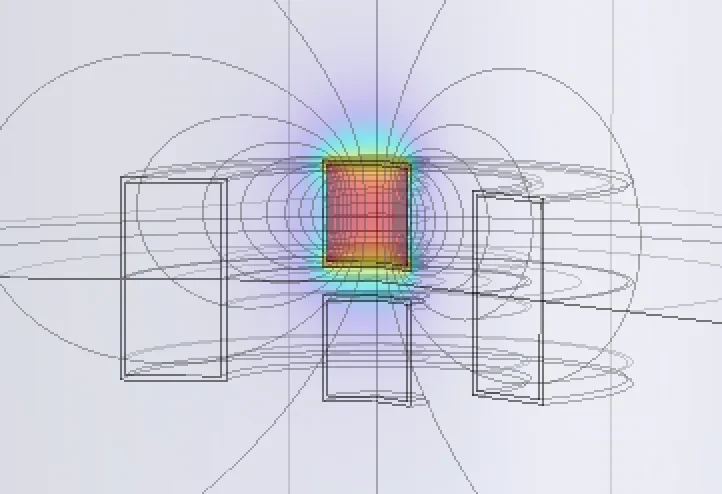
These are separate distance and current sweeps, not a full parameter map. A force is available only at 0.4 A, at 0.8 mm, or at 0.2 mm for the 3 mm magnet. Other combinations were not simulated. The distance sweep is labelled 0.4 A because its values match that current sweep; the report does not state the current. The 1 mm magnet gives different values where the two sweeps meet.
Force data
| mm | 3 mm cylinder | 2 mm cylinder | 1 mm cylinder |
|---|---|---|---|
| 0.2 | 0.429 | 0.082 | 0.013 |
| 0.3 | 0.558 | 0.097 | 0.024 |
| 0.5 | 0.628 | 0.145 | 0.042 |
| 0.6 | 0.676 | 0.157 | 0.039 |
| 0.7 | 0.747 | 0.18 | 0.039 |
| 0.8 | 0.813 | 0.17 | 0.034 |
| 1.2 | 0.345 | 0.12 | 0.033 |
| 1.4 | 0.282 | 0.112 | 0.032 |
| 1.6 | 0.155 | 0.089 | 0.032 |
| 1.8 | 0.101 | 0.049 | 0.032 |
| 2 | 0.022 | 0.006 | 0.02 |
| A | 3 mm cylinder | 2 mm cylinder | 1 mm cylinder | 3 mm, 0.2 mm |
|---|---|---|---|---|
| 0.2 | 0.43 | 0.03 | 0.015 | 0.109 |
| 0.3 | 0.588 | 0.088 | 0.028 | 0.241 |
| 0.4 | 0.81 | 0.17 | 0.046 | 0.428 |
| 0.5 | 1.094 | 0.275 | 0.07 | 0.667 |
| 0.6 | 1.441 | 0.402 | 0.099 | 0.959 |
| 0.7 | 1.852 | 0.553 | 0.133 | 1.304 |
| 0.8 | 2.324 | 0.727 | 0.172 | 1.702 |
Simulation values digitised from report figures 4.6–4.10. Distance sweep at 0.4 A (inferred).
Repulsive force between two magnets
The actuators sit on opposite sides of the septum with like poles facing. Compare simulated and measured repulsion as magnet geometry and separation change.
- Gap between the magnets
- 1 mm
- Simulation
- 0.54 N
- Measured
- 0.54 N
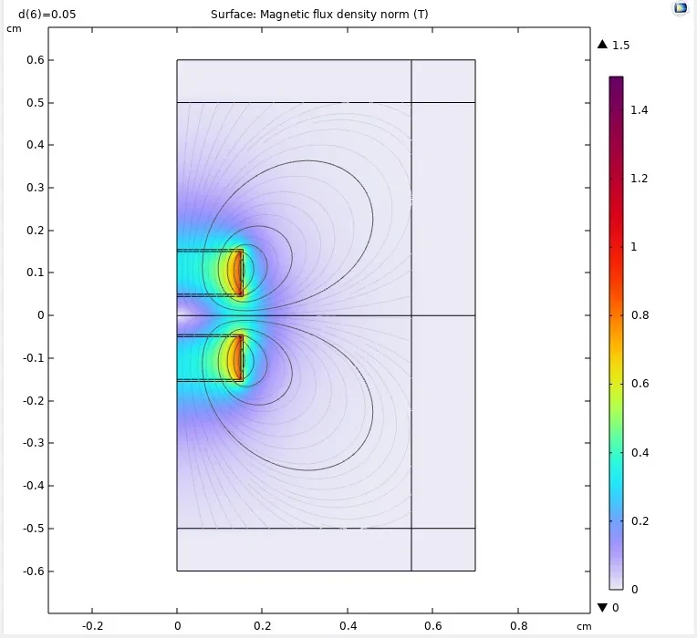
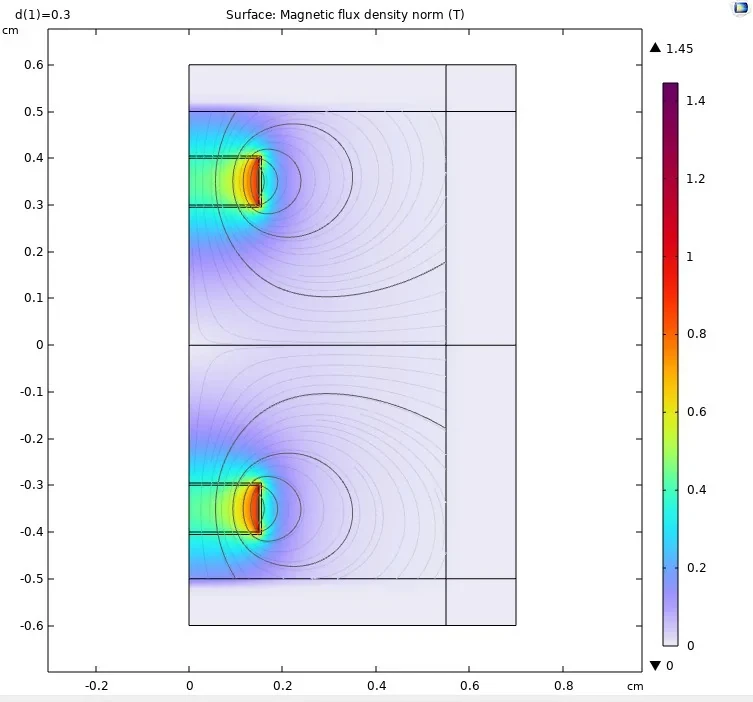
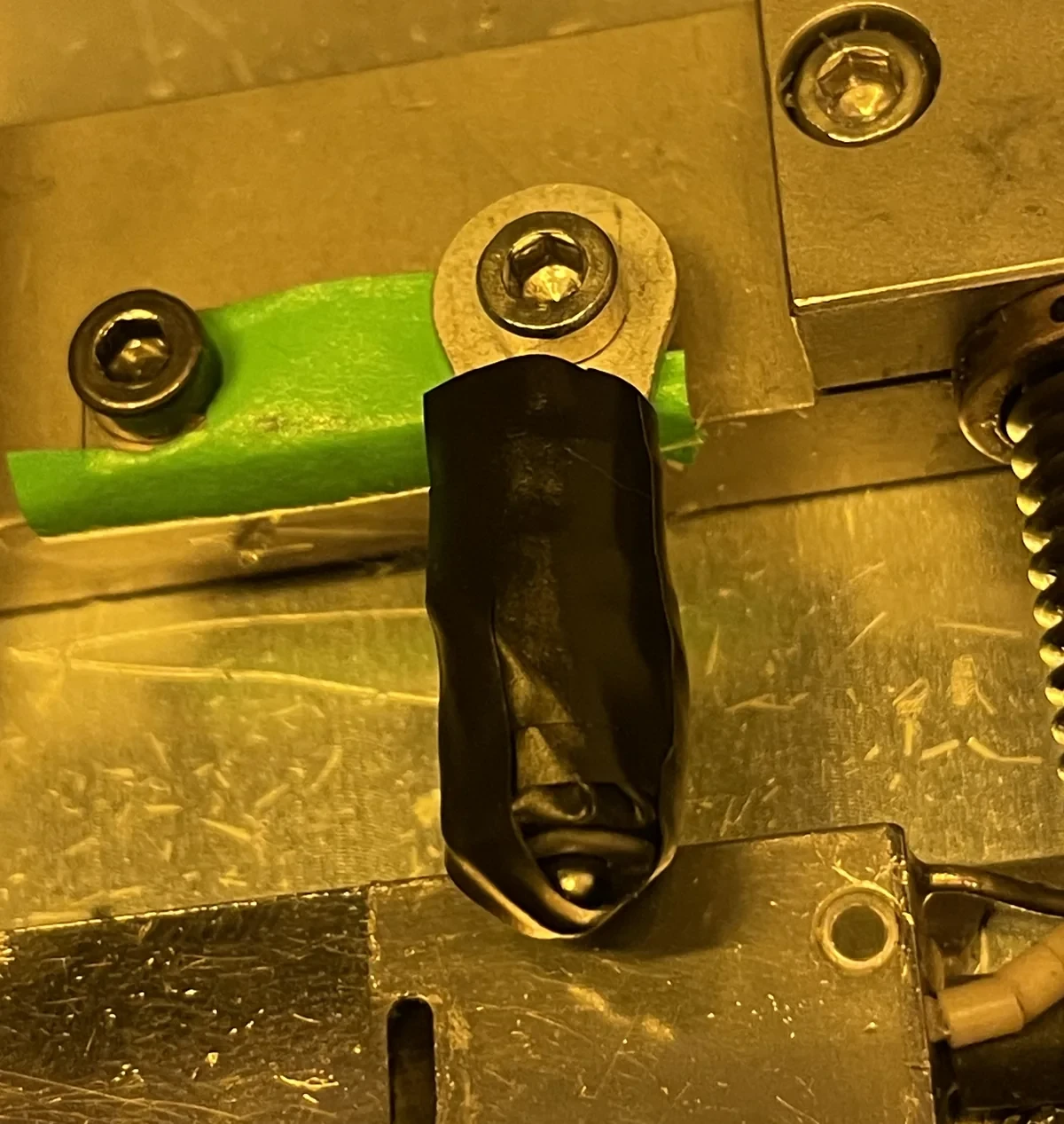
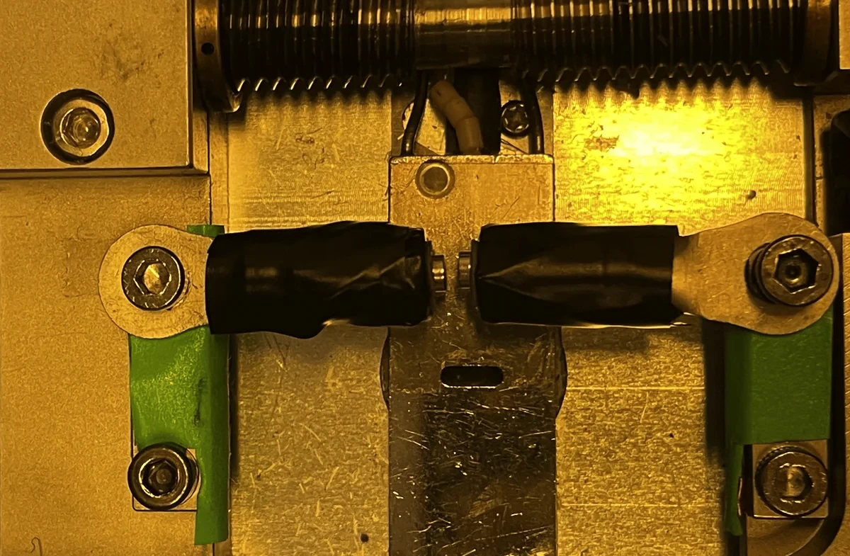
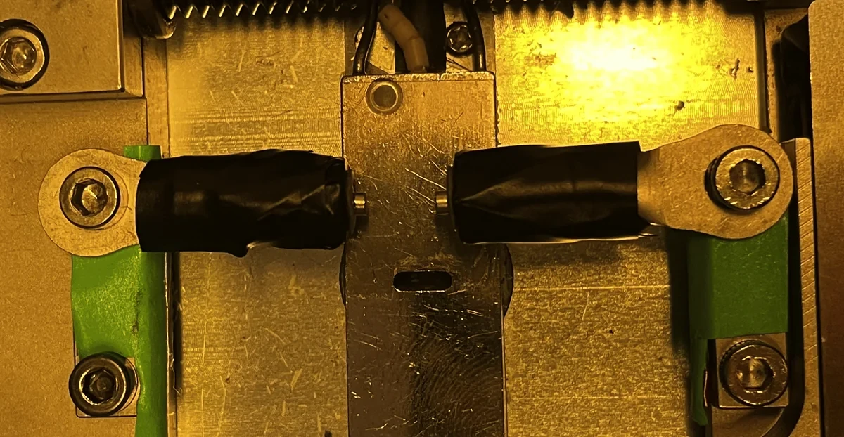
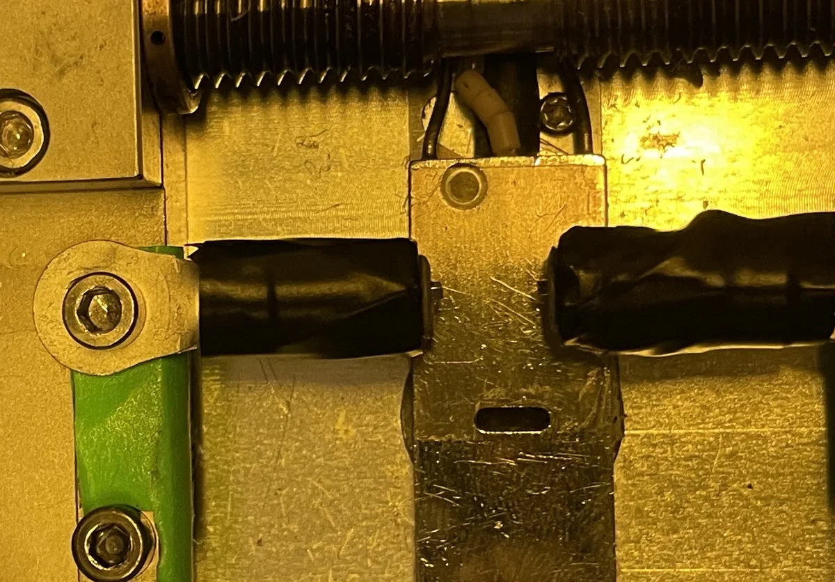
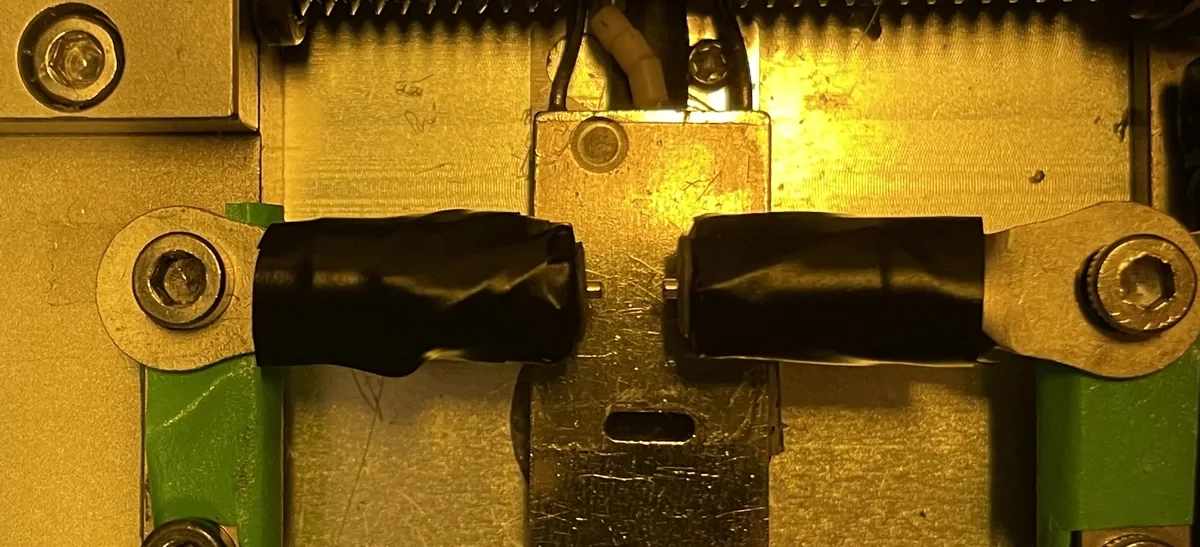
For the measurements, one magnet was mounted on a force sensor and the other on a moving stage. The gap was reduced from 6 to 1 mm. The sensor resolution was 0.01 N; values below it are shown as below resolution.
Force data
| mm | 3 mm sphere | 3 mm cylinder | 2 mm cylinder | 1 mm square | 1 mm cylinder |
|---|---|---|---|---|---|
| 1 | 0.567 / 0.51 | 0.538 / 0.54 | 0.218 / 0.18 | 0.057 / 0.03 | 0.03 / 0.03 |
| 2 | 0.233 / 0.16 | 0.196 / 0.21 | 0.062 / 0.07 | 0.017 / 0.01 | 0.006 / 0.01 |
| 3 | 0.113 / 0.07 | 0.084 / 0.09 | 0.023 / 0.02 | 0.007 / 0 | 0.002 / 0 |
| 4 | 0.036 / 0.01 | 0.04 / 0.05 | 0.01 / 0.01 | 0.003 / 0 | 0.001 / 0 |
| 5 | 0.015 / 0 | 0.021 / 0 | 0.005 / 0 | 0.002 / 0 | 0.0005 / 0 |
| 6 | 0.007 / 0 | 0.01 / 0 | 0.002 / 0 | 0.002 / 0 | 0.0002 / 0 |
Simulation and measurement values digitised from report figures 4.12 and 4.13.
My contribution
I designed the two-channel amplifier board, implemented the PWM drive and modelled the coil–magnet system, then tested independent actuator control.