
industry · Mar – Aug 2026
A six-axis force sensor for robot joints
An inductive sensor that measures three forces and three torques for robotic interaction.
Project details
-
Force and torque sensing
A robot needs force and torque measurements to control contact with its surroundings. A six-axis sensor measures three force components and three torque components. Most designs bond strain gauges to a compliant structure, but gauges drift with temperature and are delicate to assemble in volume.
-
Inductive measurement of deformation
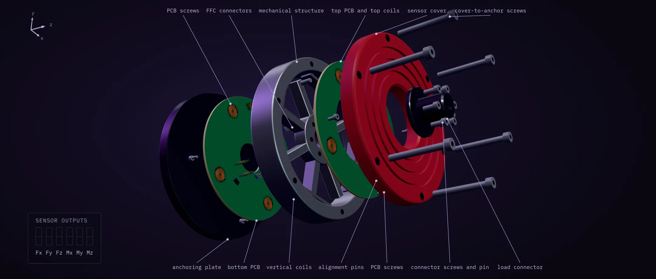
This design uses coils on two circular boards to measure deformation of a compliant aluminium part. The company defined the sensing principle and product direction. I led the project and carried out almost all of the development, from mechanical design and electronics to acquisition and calibration, with advice from the team.
-
Optimising stiffness and sensitivity
782 FEM evaluations
The structure must deform enough to resolve small forces while remaining sufficiently stiff for a robot joint. I parameterised its geometry and ran a global optimisation with 782 FEM evaluations. The result is a Pareto front rather than a single answer, which makes the trade-off between stiffness and sensitivity visible before choosing the geometry.
-
Fatigue assessment
The final geometry reaches 187 MPa under a 25 N·m load, below the aluminium’s nominal one-million-cycle strength of 202 MPa. Applying the corrected fatigue envelope’s knock-down factors lowers the allowable stress below every evaluated load case. So the design meets the nominal limit, but not the corrected one.
-
Calibration and sources of error
I calibrated the sensor against a reference wrench using seven recordings. I separated the residual error into non-linearity, zero drift after warm-up and hysteresis during unloading, and assessed cross-axis coupling. Splitting the error this way shows which term to work on next, instead of hiding everything in one accuracy figure.
-
Prototype demonstration
0.36 %FS accuracy · 9.1 bits effective resolution
The demonstration shows the measured force and torque traces responding as the handle is pushed and twisted, with a cube visualising the motion. Calibration against the reference wrench gave 0.36 %FS accuracy, 9.1 bits of effective resolution and 0.13 % cross-axis coupling. In a next version, I would start from the corrected fatigue allowable.
My contribution
I led the sensor project and carried out almost all of the mechanical design, FEM optimisation, readout electronics, acquisition and calibration. The rest of the team provided advice throughout.